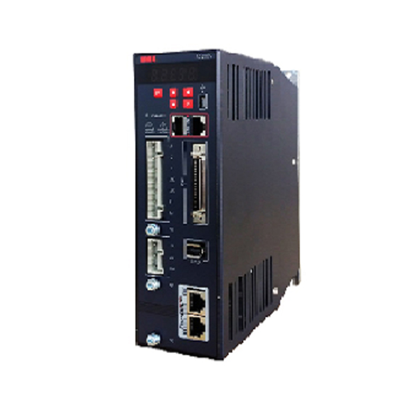
HSD3 series high-end synchronous servo drive
HSD3 series high-end synchronous AC servo driver adopt the advanced control algorithm, support mainstream protocol such as MODBUS, CANOPEN,EtherCAT, MECHATROLINK which can realize speed and accurate position control. With intelligent power module (IPM) and other latest technology design, simple operation, high reliability, small size, easy to install.
Cover a big range of servo motor, support three phase AC220V and 380V power supply.
Support 17bit increamental and 17bit/23bit absolute type encoder.
This servo driver has mature servo technology and the highest cost performance.
1.Main circuit power supply: Three-phase AC220V, 50/60Hz; Three-phase AC380V, 50/60Hz;
2. Control mode: Position control, JOG operation, speed contact, etc.
3. Encoder feedback:
Ordinary incremental encoder: 2500 lines incremental standard type, 2500 lines incremental saving line type.
Serial encoder:17bits incremental type encoder, 17bits/ 23bits absolute value encoder.
4. Communication: Standard MODBUS, CANOPEN,EtherCAT, MECHATROLINK.
5. Speed control range: 1:10000( in the stable running without crawling at the rated load);
6. Digital Input terminal: photoelectric coupling isolation, functional programmable, can realize servo ON (/ S – ON), P action (/P – CON), not forward the side drive (P – OT), not reverse side drive (N-OT), alarm reset (/ALM-RST), forward side torque limit (/P-CL), internal set speed switch and so on
7. Digital output terminal: functional programmable, can realize servo alarm (ALM), position completion (/COIN), speed consistency inspection (/V-CMP), servo motor rotation detection (/TGON), servo readiness (/S-RDY), torque limit detection (/CLT), brake (/BK), encoder zero output (PGC).
8. Over travel (OT) prevention function: Dynamic brake (DB) stopping, decelerate stopping, or free running stop when it is at P-OT, N-OT input action
9.Protection function: Over current, overvoltage, under voltage, overload, over speed, regeneration fault, encoder feedback error, etc
|
HSD3 Model |
03A□□ |
06 A□□ |
10 A□□ |
16 A□□ |
25 A□□ |
|
|
Continuous output current (A) |
3.0 |
6.0 |
10 |
16 |
25 |
|
|
Main circuit power supply |
Three-phase AC200~230V(-15~+10%) 50/60Hz |
|||||
|
Control Power source |
Single-phase AC200~230V(-15~+10%) 50/60Hz |
|||||
|
Control mode |
Position control, JOG operation, speed contact, etc. |
|||||
|
Encoder feedback |
Ordinary incremental encoder: 2500 lines incremental standard type, 2500 lines incremental saving line type. |
|||||
|
Serial encoder:217 bits incremental type encoder, 217/216 bits absolute value encoder, 223/216 bits absolute value encoder. |
||||||
|
Conditions of usage |
Using ambient temperature/storage temperature. |
Using ambient temperature:0~+50℃,storage temperature:-20~+85℃. |
||||
|
Environmental humidity/storage humidity. |
Less than 90%RH(No freezing or condensation) |
|||||
|
Vibration/impact strength resistance |
4.9m/s2/19.6m/s2 |
|||||
|
Structure |
Pedestal mounting type |
|||||
|
Performance |
Speed control range |
1:10000(The lower limit of the speed control range is in the stable running without crawling at the rated load) |
||||
|
Speed response |
1KHz |
|||||
|
Velocity volatility (load variation) |
0~100% loading : less than ±0.01%(in rated speed) |
|||||
|
Velocity volatility rate (voltage variation) |
Rated voltage ±10%:0%(in rated speed) |
|||||
|
Velocity volatility rate (voltage variation) |
25±25℃:less than ±0.1%(in rated speed) |
|||||
|
Simulation speed Command Input |
Command voltage |
DC±10V |
||||
|
Input impedance |
About 20KΩ |
|||||
|
Circuit time parameter |
47μs |
|||||
|
Simulation torque Command Input |
Command voltage |
DC±10V |
||||
|
Input impedance |
About 20KΩ |
|||||
|
Circuit time parameter |
47μs |
|||||
|
Sequence control input Signal |
Number of points |
8 points |
||||
|
Function (distributable) |
Servo ON (/ S – ON), P action (/P – CON), not forward the side drive (P – OT), not reverse side drive (N-OT), alarm reset (/ALM-RST), forward side torque limit (/P-CL), reverse side torque limit (/N-CL), zero position deviation (/CLR), internal set speed switch and so on The distribution of the above signals and the change of positive/negative logic |
|||||
|
Sequence control output Signal |
Number of points |
6 points |
||||
|
Function (distributable) |
Servo alarm (ALM), position completion (/COIN), speed consistency inspection (/V-CMP), servo motor rotation detection (/TGON), servo readiness (/S-RDY), torque limit detection (/CLT), brake (/BK), encoder zero output (PGC). The distribution of the above signals and the change of positive/negative logic |
|||||
|
Encoder frequency division pulse output |
A phase, B phase, C phase: linear drive output; frequency division pulse number: it can be set arbitrarily |
|||||
|
RS-485 Newsletter |
Communication protocol |
MODBUS |
||||
|
1:N communication |
The maximum can be N = 127 stops |
|||||
|
Axis address setting |
Via parameter setting |
|||||
|
CAN communication |
Communication protocol |
CANOpen(DS301 + DS402 profile) |
||||
|
1:N communication |
The maximum can be N = 127 stops |
|||||
|
Axis address setting |
Via parameter setting |
|||||
|
Display function |
CHARGE indicator light, 7 segment digital tube 5 bits |
|||||
|
Regenerative treatment |
Built-in regenerative resistors or external regenerative resistors (selected parts) |
|||||
|
Over travel (OT) prevention function |
Dynamic brake (DB) stopping, decelerate stopping, or free running stop when it is at P-OT, N-OT input action |
|||||
|
Protection function |
Over current, overvoltage, under voltage, overload, over speed, regeneration fault, encoder feedback error, etc. |
|||||
|
Monitoring function |
RPM current position, instruction pulse accumulation, position deviation, motor current, running state, input and output signal, etc. |
|||||
|
Secondary functional |
Gain adjustment, alarm record, JOG operation, origin search, movement of inertia test, etc. |
|||||
|
Intelligent function |
Built-in gain automatic tuning function |
|||||
|
Applicable load inertia |
Less than 5 times of the inertia motor |
|||||
|
Position control |
Feed forward compensation |
0 to 100% (setting unit 1%) |
||||
|
Type of input pulse |
Symbol + pulse sequence, CW+CCW pulse sequence, 90° phase difference two phase pulse (A phase +B phase) |
|||||
|
Input pulse form |
Support linear drive and collector open circuit |
|||||
|
The maximum input pulse frequency |
Linear drive Symbol + pulse sequence, CW+CCW pulse sequence: 500K pps 90° phase difference two phase pulse (A phase +B phase): 500K pps Collector open circuit Symbol + pulse sequence, CW+CCW pulse sequence: 200K pps 90° phase difference two phase pulse (A phase +B phase): 200K pps |
|||||
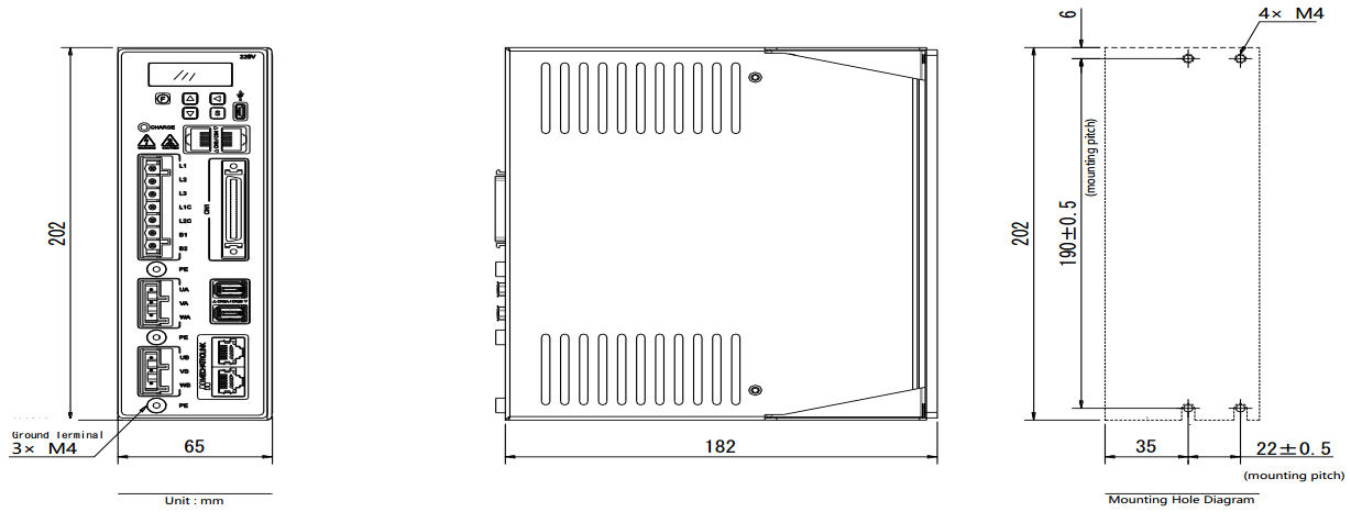
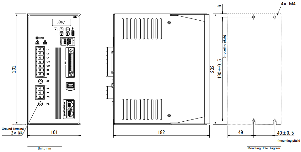
Product Outline, Mounting Dimension, and Weight:

HSD3D□-03/06/10 Exterior Dimensions

HSD3D□-16/25 Exterior Dimensions
Series
Model
Download
Servo Drive
HSD3 User Manual

